DIY Ambilight System
A kind of a smart backlight system for a TV spotted in a commercial several years ago immediately draw my attention. When I encountered the relatively affordable individually controllable RGB LED strips, I could not resist to try to make my own version of the so-called ambilight system.
DIY Ambilight System
What it is and what it is used for?
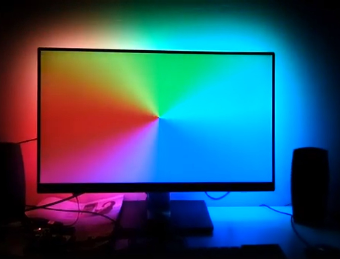
Ambilight system is a sophisticated backlight for a TV or a PC monitor (which is the case described here). It accommodates the color and intensity of the light according to the current color content of the screen, more specifically to the content present at the screen borders. As such, it visually extends the picture displayed on the monitor and it significantly improves the movie watching or gameplay experience.
Architecture of the DIY solution
The arrangement of the proposed ambilight system is shown in the following image.
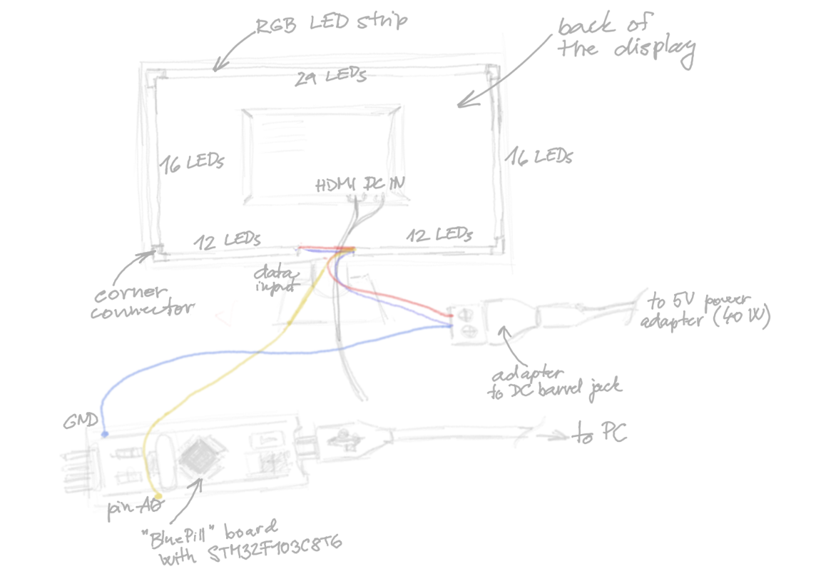
In total, there are 85 RGB LEDs on the back side of the monitor placed around its circumference. Each of these LEDs can be controlled separately via a serial data interface. The brightness of the individual red, blue and green color components is encoded by an 8 bit value and transmitted as a series of voltage pulses - a short one standing for logical 0 and a long one standing for logical 1. Generation of these control signals is the responsibility of a microcontroller.
Since the LED drivers support daisy-chaining, only a single shared data line is sufficient for control of the whole strip. The cost for this is the decrease in the refresh frequency with the rising number of LEDs, which is, however, not a problem at this scale. When connecting the individual segments of the LED chain (top, left side, etc.), mind the orientation of the strip, since one of its ends always acts just like a data input, while the other acts as data output. This direction is indicated by little arrows in between the LEDs.
I used a so-called, BluePill board, which was supposed to be equipped with an STM32F103C8T6 Cortex M3 microcontroller. As it, however, showed up, the one I bought was a fraudulent one, but fortunately, it still behaved according to the ST datasheet. I used Platformio as a development environment and LibOpenCM3 as a library for more convenient usage of the chip peripherals. If I should do the work again, I would, however, not use any of such libraries (neither LibOpenCM3 nor ST’s HAL (Hardware Abstraction Layer) or LL (Low Level) drivers) and instead, I would manipulate the MCU registers myself and create my own abstraction layer. I think this would bring me more joy from detailed understanding of the platform and probably at the same time save me quite a bit of time spend on debugging foreign code and guessing how to use the poorly documented libraries.
All of the interconnected LEDs are powered over a shared power rail. To avoid visible and distracting variations in LED brightness over the length of the strip caused by an uneven power distribution, interconnect the corresponding voltage terminals on the two of its ends. The wattage of the source has to be sufficiently high, for 85 LEDs the minimum should be 25.5W (it has to provide at least 5.1 A at 5 V, which is given by the fact that each of the 85 RGB LEDs consumes 60mA at its maximum brightness). I used a higher-rated 40 W power source adapter to have some margin and be able to use it later in other projects with even more LEDs.
The color information for individual LEDs is obtained by grabbing the screen content using a Python script and computing an average value from a small patch around each of the LED. An array of these values is then send over through a virtual COM port oven a USB cable and received by the BluePill board. The contained MCU then drives the LEDs as was already mentioned above. On my machine I was easily able to achieve a framerate greater then 30 fps - more then sufficient for movie watching purposes. Details can be seen directly from code shared at projects Git repository.
Summary of the used parts
In the following table there is a summary of all the used components including prices at the time. All of them were purchased on Aliexpress.com from various chinese vendors.
| Name | Price | Image |
|---|---|---|
| Bluepill board with ARM MCU | $1.73 | 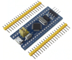 |
| 2m of IP30 black LED strip with adhesive tape containing 60 WS2812 (Neopixel LEDs) per meter | $6.55 | 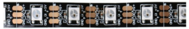 |
| Female DC Barrel Jack Adapter for connecting the LED strip to the power supply adapter | $0.79 |  |
| 5V, 40W power supply | $12.12 | 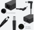 |
| optionally a 3 pin corners for solder-free connection of LED strips (in the end I soldered the corners to the strips instead of using the solder free connectors, because these provided very poor electrical connection) | $4.53 | 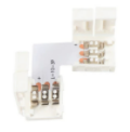 |
Total: $25.72
Programming the chip
Apart from this you will also need some programmer to flash the STM32 chip. To this purpose I used the STLink present on my ST’s Nucleo boards. Just follow the manual to properly set the couple of configuration jumpers. Programming of the chip itself is performed over SWD interface. It is sufficient to connect the respective SWCLK, SWDIO and GND pins on the programmer with their counterparts on the BluePill board. Furthermore, connect the 3.3V pin of the BluePill board to the VDD_TARGET pin on the programmer. Keep in mind that the BluePill board has no built-in protections on its pins and thus, for example, be sure you provide it with power just from a single source (e.g. either from the Nucleo board programmer or from the USB interface, when it is already connected to a PC).
Testing the final assembly